- 您现在的位置:买卖IC网 > Sheet目录341 > MAX7307AUB+T (Maxim Integrated)IC LED DRIVER LINEAR 10-UMAX
SMBus/I 2 C Interfaced 4-Port, Level-Translating
GPIOs and LED Drivers
recipients. When the MAX7306/MAX7307 transmit to the
master, the master generates the acknowledge bit
because the master is the recipient.
Slave Address
The MAX7306/MAX7307 have a 7-bit long slave
address (Figure 12). The 8th bit following the 7-bit slave
address is the R/ W bit. Set the R/ W bit low for a write
command and high for a read command.
The first 5 bits of the MAX7306 slave address (A6–A2)
are always 1, 0, 0, 1, and 1. Slave address bits A1 and
A0 are selected by the address input AD0. AD0 can be
connected to GND, V DD , SDA, or SCL. The MAX7306
has four possible slave addresses (see Table 5), and
therefore, a maximum of four MAX7306 devices can be
controlled independently from the same interface. The
MAX7307 features a permanent slave address of 0x98.
Message Format for Writing to the MAX7306/MAX7307
A write to the MAX7306/MAX7307 comprises the trans-
mission of the MAX7306/MAX7307’s slave address with
the R/ W bit set to zero, followed by at least 1 byte of
information. The first byte of information is the command
byte. The command byte determines which register of
the MAX7306/MAX7307 is to be written to by the next
byte, if received (see Table 1). If a STOP condition is
detected after the command byte is received, the
MAX7306/MAX7307 take no further action beyond stor-
ing the command byte (see Figure 13).
Any bytes received after the command byte are data
bytes. The first data byte goes into the internal register of
the MAX7306/MAX7307 selected by the command byte
(see Figure 14). If multiple data bytes are transmitted
before a STOP condition is detected, these bytes are
generally stored in subsequent MAX7306/MAX7307
internal registers because the command byte address
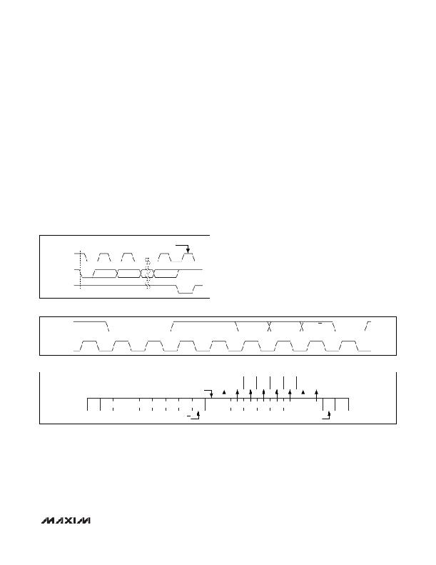
START
CONDITION
CLOCK PULSE
FOR ACKNOWLEDGE
autoincrements (see Table 1).
SCL
1
2
8
9
Message Format for Reading
The MAX7306/MAX7307 are read using the MAX7306/
SDA BY
TRANSMITTER
SDA BY
MAX7307 ’s internally stored command byte as an
address pointer the same way the stored command byte
is used as an address pointer for a write. The pointer
RECEIVER
S
autoincrements after each data byte is read using the
Figure 11. Acknowledge
SDA
1
0
0
1
1
1
A0
R/W
ACK
MSB
SCL
Figure 12. Slave Address
LSB
D15
D14
D13
D12
D11
D10
D9
D8
ACKNOWLEDGE FROM MAX7306
S
SLAVE ADDRESS
0
A
REGISTER ADDRESS
A
P
Figure 13. Register Address Received
R/W
ACKNOWLEDGE FROM MAX7306
______________________________________________________________________________________
19
发布紧急采购,3分钟左右您将得到回复。
相关PDF资料
MAX831EVKIT-SO
EVAL KIT FOR MAX831
MAX8513EVKIT
EVAL KIT FOR MAX8513
MAX8552EUB+
IC DRIVER MOSFET HS 10-UMAX
MAX8595XETA+T
IC LED DRIVR WHITE BCKLGT 8-TDFN
MAX8607ETD+T
IC LED DRIVR PHOTO FLASH 14-TDFN
MAX8608YETD+T
IC LED DRVR WT/OLED BCKLT 14TDFN
MAX8631XETI+T
IC LED DRVR WHITE BCKLGT 28-TQFN
MAX8645YETI+T
IC LED DRVR WHITE BCKLGT 28-TQFN
相关代理商/技术参数
MAX7307EVKIT+
制造商:Maxim Integrated Products 功能描述:MAX7307 EVAL KIT/EVAL SYS - Rail/Tube
MAX730A
制造商:MAXIM 制造商全称:Maxim Integrated Products 功能描述:5V, Step-Down, Current-Mode PWM DC-DC Converters
MAX730AC/D
功能描述:直流/直流开关转换器 DICE SALES DICE RoHS:否 制造商:STMicroelectronics 最大输入电压:4.5 V 开关频率:1.5 MHz 输出电压:4.6 V 输出电流:250 mA 输出端数量:2 最大工作温度:+ 85 C 安装风格:SMD/SMT
MAX730AC/D DIE
制造商:Maxim Integrated Products 功能描述:
MAX730ACPA
功能描述:直流/直流开关转换器 5V Step-Down DC/DC Converter RoHS:否 制造商:STMicroelectronics 最大输入电压:4.5 V 开关频率:1.5 MHz 输出电压:4.6 V 输出电流:250 mA 输出端数量:2 最大工作温度:+ 85 C 安装风格:SMD/SMT
MAX730ACPA+
功能描述:直流/直流开关转换器 5V Step-Down DC/DC Converter RoHS:否 制造商:STMicroelectronics 最大输入电压:4.5 V 开关频率:1.5 MHz 输出电压:4.6 V 输出电流:250 mA 输出端数量:2 最大工作温度:+ 85 C 安装风格:SMD/SMT
MAX730ACSA
功能描述:直流/直流开关转换器 5V Step-Down DC/DC Converter RoHS:否 制造商:STMicroelectronics 最大输入电压:4.5 V 开关频率:1.5 MHz 输出电压:4.6 V 输出电流:250 mA 输出端数量:2 最大工作温度:+ 85 C 安装风格:SMD/SMT
MAX730ACSA+
功能描述:直流/直流开关转换器 5V Step-Down DC/DC Converter RoHS:否 制造商:STMicroelectronics 最大输入电压:4.5 V 开关频率:1.5 MHz 输出电压:4.6 V 输出电流:250 mA 输出端数量:2 最大工作温度:+ 85 C 安装风格:SMD/SMT
